Products
Fire Valves
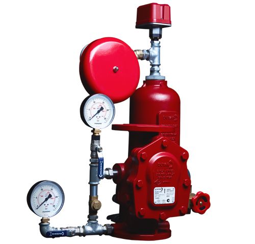
| The wet alarm valve is designed for applications where there is no risk of water freezing. Pressurized water held in the pipes is discharged into the fire area when sprinklers are activated due to a fire. The pressurized water system continuously feeds while simultaneously filling the delay chamber. Once the chamber is filled, the pressure switch on the chamber triggers, sending an alarm signal to the fire alarm system or automation system. After the pressure switch is triggered, water reaches the water motor gong, providing mechanical alarm. Specifically designed for all wet pipe systems. Prevents false alarms under different pressures with its sensitive delay chamber. Suitable for upright installation with trim kit. Semi-assembled. | |
| Download Document | |

| The dry pipe sprinkler system is designed for places where pipes and sprinklers may be exposed to freezing temperatures, such as unheated warehouses, garages, parking garages, attics, and stores. The sprinkler system contains air or nitrogen gas instead of water. The differential type dry alarm valve prevents the entry of water at low pressure with air and at high pressure with water into the system through its special flap. During any fire, the differential ratio in the system is disturbed due to the bursting sprinklers, causing the flap to open. The pressure switch sends an alarm signal to the fire alarm system or automation system. After the pressure switch is triggered, water reaches the water motor gong, causing a mechanical alarm to sound. Specifically designed for all dry pipe systems. Externally resettable. Suitable for upright installation only. Semi-assembled. | |
| Download Document | |
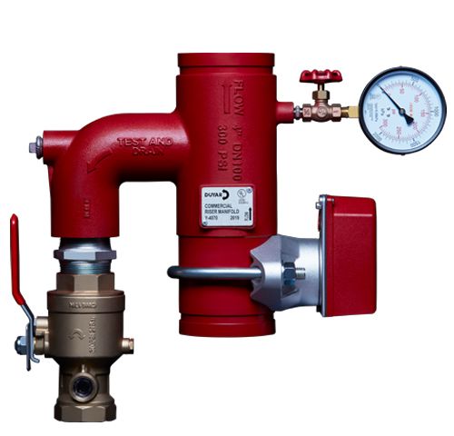
| The Easy Installation Unit is designed to expedite installation processes in wet fire suppression systems, complying with NFPA requirements. In the event of a fire, the flow switch generates a signal due to the flow occurring in the system, sending a signal to the control panel or electrical gong to determine where the fire is located, whether on which floor, zone, or branch. The sprinkler system can be tested instantly and the system can be drained thanks to the orifice on the test and drain valve on it. The Easy Installation Unit consists of a flow switch, 3-way manifold control valve, pressure gauge, and appropriate test and drain valve. | |
| Download Document | |
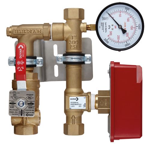
| The Gear Type Easy Installation Unit - Residential Riser Manifold is designed to expedite installation in wet fire suppression systems, in compliance with NFPA requirements. In case of fire, a signal is generated with a Flow Switch on it. This signal is sent to a control panel to indicate the fire zone or line. The Test & Drain valve on it allows the sprinkler system to be instantly tested or drained of water. The residential riser manifold includes a flow switch, a pressure gauge, and a test & drain valve. | |
| Download Document | |

| The Traceable Butterfly Valve - Wafer Type is defined as a regional control valve. It is used as a cut-off valve on water supply lines to separate (control) zones within a building. Butterfly valves or rising stem valves are used for cutting off or controlling purposes. The position of all valves used in fire systems must be visible and electrically traceable. Butterfly valves are of the gear-operated type with a gearbox and handwheel. The monitoring switch of the butterfly valves is inside the valve and has an open-closed position indicator. | |
| Download Document | |
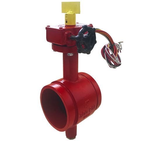
| The Traceable Butterfly Valve - Grooved Type is defined as a regional control valve. It is used as a cut-off valve on water supply lines to separate (control) zones within a building. Butterfly valves or rising stem valves are used for cutting off or controlling purposes. The position of all valves used in fire systems must be visible and electrically traceable. Butterfly valves are of the gear-operated type with a gearbox and handwheel. The monitoring switch of the butterfly valves is inside the valve and has an open-closed position indicator. | |
| Download Document | |
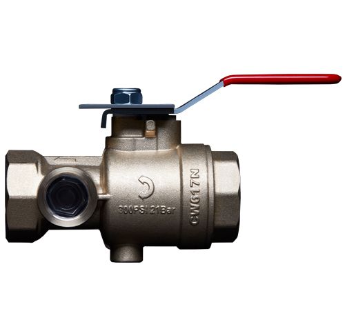
| Test and drain valves are used for conducting tests and maintenance in sprinkler systems. With its various sizes of orifices, it ensures equal flow to the flow passing through just one sprinkler, enabling controlled testing of alarm devices in the lines when a sprinkler water flow occurs. The orifice diameter of the smallest sprinkler and the test drain valve in the system must be equal. These valves can also be used as drain valves by changing their position to drain water from the pipes. They have a sight glass for flow observation. | |
| Download Document | |
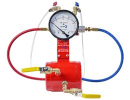
| Used to check if pump systems are passing the desired flow rate at specified intervals. The flow meter is usually installed on a branch taken from the pump discharge lines between the check valve and the OS&Y valve. The diameter of the flow meter is determined based on the pump flow rate. | |
| Download Document | |
|
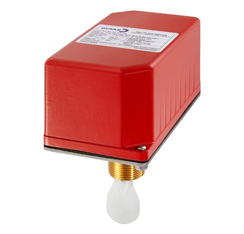
• Dirt trap should be used in the installation where the pressure switch will be mounted and the water flow should be free of dirt. The product will not operate in water flow containing dirt and particles.
• The pressure switch should be mounted vertically as seen in the figures. • Authorized personnel with expertise in electrical devices should start the installation according to the following installation sequence. • After wrapping the 1⁄2” threaded part of the product with Teflon tape, it should be mounted to the 1⁄2” installation. Excessive torque should not be applied during installation to the installation. • The red protective cover is removed using the special key found in the box for electrical connection. • After removing the red protective cover, NO, NC and COM sections are visible on the switch. • Visual or audible alarms can be obtained from these sections. A signal can be sent to the fire control panel. • Product pressure adjustment can be made within the frame. After setting the product to the desired pressure range, the red protective cap should be screwed closed with screws. • After the installation of the product is completed, it should be checked whether a signal is received from the product at least 3 times. • Leakage and signal problems should be checked periodically every month with the test valve on the line. The product should not be used if leakage and signal problems occur. |
|
| Download Document | |

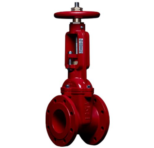
| They are defined as regional control valves. They are used as shut-off valves on water supply lines to separate (control) internal zone areas. Butterfly valves or rising stem gate valves are used for cutting or control purposes. Rising stem gate valves are a type of sliding valve that does not disrupt smooth flow in the fully open position, can be visually monitored with the up and down movement of the stem, and can be electrically monitored by attaching a monitoring switch. They create less hydraulic loss compared to butterfly valves. | |
| Download Document | |

| Rising Stem Sliding Valve (OS&Y) | Y-4045 is defined as a regional control valve. It is used as a shut-off valve on water supply lines to separate (control) internal zone areas. Butterfly valves or rising stem gate valves are used for cutting or control purposes. Rising stem gate valves are a type of sliding valve that does not disrupt smooth flow in the fully open position, can be visually monitored with the up and down movement of the stem, and can be electrically monitored by attaching a monitoring switch. They create less hydraulic loss compared to butterfly valves. | |
| Download Document | |
| The OS&Y rising stem valve monitoring switch uses control switches to monitor the open/close position of the valve. It detects the up and down movement of the stem when the valve opens or closes, enabling electrical signaling. | |
| Download Document | |
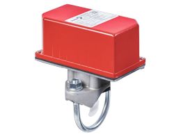
| Flow switches are used in sprinkler systems to send electrical signals to the system when any sprinkler activates, preventing false alarms. Delay units are available to prevent false alarms. Our Flow Switch product is manufactured domestically in Turkey and exported worldwide. We take pride in being the first in Turkey to produce Flow Switches! | |
| Download Document | |
| The threaded flow switch is a wing-type water flow switch designed for use in wet sprinkler systems using 1" (25mm), 1 ¼" (32mm), 1 ½" (38mm), or 2" (50mm) pipe sizes. The unit can also serve as a sectional water flow detector in large systems. The unit includes two single-pole double-throw snap action switches and an adjustable, instant resetting pneumatic delay. The flow switch can be mounted in both horizontal and vertical positions. | |
| Download Document | |

X
We use legal cookies to provide you with a better service. For information COOKIE POLICY ve PRIVACY POLICY Check out our sections.